CSF17-XRB
2019-04-09
-
Part NO.
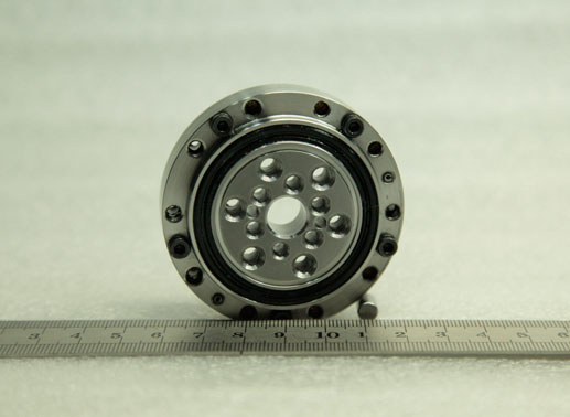
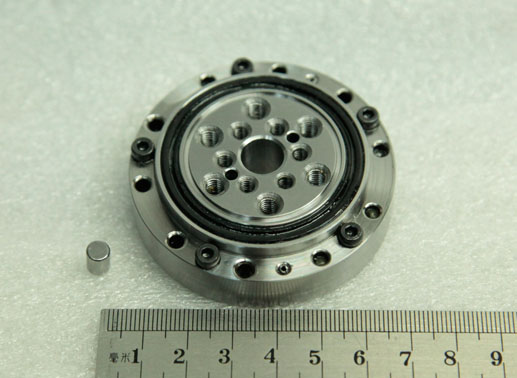
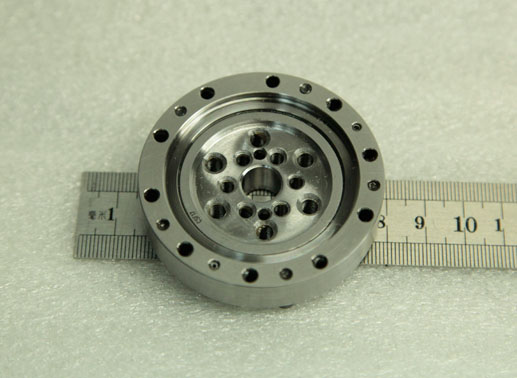
Open type:CSF17-XRB
-
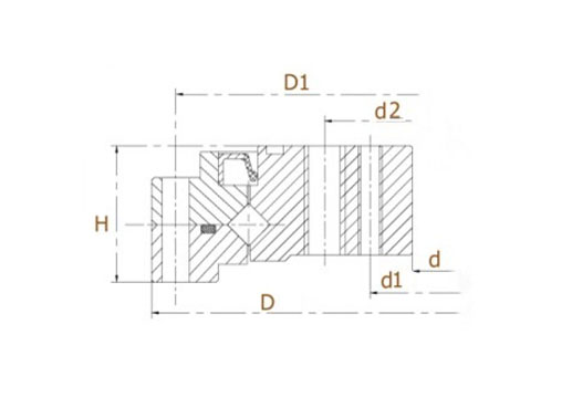
Dimension
d:10mm
D:62mm
H:16.5mm
-
Mounting
d1:17.5mm
d2:27mm
D1:56mm
-
Basic Load Ratings
-
Equivalent Model
Mass:0.27kg
- Features
- Mounting
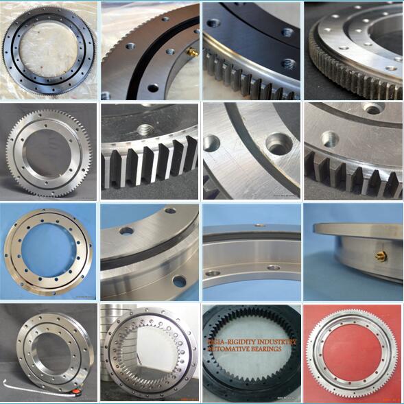
CSF17 harmonic reducer output bearing specifications:
Type of guide Roller Space retainer Yes Material GCr15 Standard lubrication method Grease lubrication Oil hole No Sealing Framework oil seal on one side Radial clearance -0.01 ~ 0 Rotation accuracy P5 Working temperature -20℃ ~ 80℃ Other CSF|CSG harmonic reducer bearing models.
CSF17-XRB harmonic speed reducer bearing features:
1. Integrated inner ring with split outer ring.
2. Sustain radial, axial and moment loads at the same time.
3. High stiffness, high rotation accuracy and high loading capacity.
4. Compact structure with mounting holes on inner and outer ring, easy to install and save space.
5. Suited for CSF, CSG series harmonic reducers.FAQ
1. What’s the rotation accuracy of this bearing CSF17-XRB?
Standard CSF17 harmonic reducer bearings precision grade is P5. Run-out of inner ring is 0.005mm, run-out of outer ring is 0.008mm. If higher running accuracy is required, please contact us.2. What is the warranty of this CSF17 drive units crossed roller bearing ?
BRS provide one year warranty for bearing products that working under common working conditions. We have excellent after-sale service to help users during the installation and application of bearings.CSF17 harmonic drive gearbox bearing instructions:
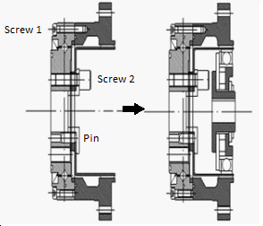
1. Before installation, please clean bearing bracket, shaft, or other components,
make sure there is no burrs or rough edge.
2. Install the locating pin to output bearing.
3. Install the Screw 1, then install the Screw 2.
4. Install the wave generator and related components.