010.30.560
2020-07-20
-
Part NO.
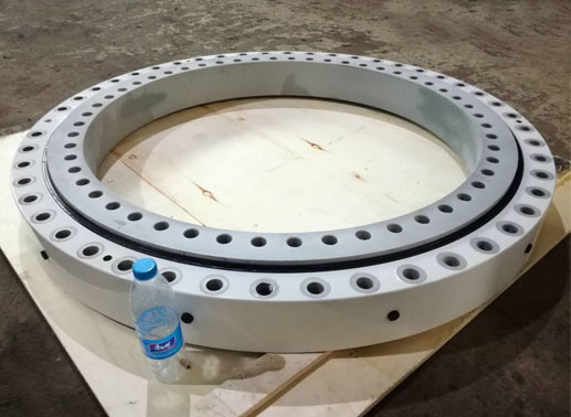
Open type:010.30.560
-
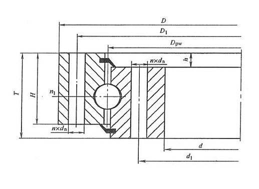
Dimension
di:458mm
Da:662mm
H:80mm
-
Mounting
Li:494mm
La:626mm
-
Basic Load Ratings
Cr:-kN
Cor:-kN
-
Gear Teeth
m:-mm
z:-mm
-
Equivalent Model
Mass:-kg
- Features
- Mounting
010.30.560 pitch bearing specifications:
Type of guide Ball Space retainer Yes Material 42CrMo Standard lubrication method Grease lubrication Oil hole Yes Sealing NBR sealed both sides Surface treatment Available Axial clearance -0.05~0 mm Rotation accuracy P5 Working temperature -15℃ ~ 80℃ Other four point contact ball pitch slewing bearing models
Model D(mm) d(mm) T(mm) D1(mm) d1(mm) n x dn 010.30.560 662 458 80 626 494 20xφ18 010.30.630 732 528 80 696 564 24xφ18 010.30.710 812 608 80 776 644 24xφ18 010.40.800 922 678 100 878 722 30xφ22 010.40.900 1022 778 100 978 822 30xφ22 010.40.1000 1122 878 100 1078 922 36xφ22 010.40.1120 1242 998 100 1198 1042 36xφ22 010.45.1250 1390 1110 110 1337 1163 40xφ26 010.45.1400 1540 1260 110 1487 1313 40xφ26 010.45.1600 1740 1460 110 1687 1513 45xφ26 010.45.1800 1940 1660 110 1877 1713 45xφ26 010.60.2000 2178 1825 144 2110 1891 48xφ33 Besides standard models above, BRS can also produce customized yaw bearings, pitch bearings and blade bearings. The production standards of common four point contact ball slewing rings are different from wind turbine slewing bearings. Check “Wind power generators yaw and pitch bearings technical requirements” for details.
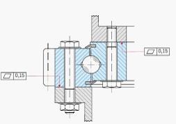
010.30.560 slewing bearing mounting instructions:

1. Make sure the mounting surface is flat and clean, and free from burrs or
rough edge.
2. The unhardened zone is marked with an “S” on the slewing ring, it must be positioned outside the main load-carrying areas.
3. Commissioning of the slewing ring under sufficient load.
4. Adjust the backlash of gear and recheck it after final tightening of the bearing.
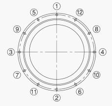
5. Fastening bolts. Place the bearing onto connecting structure and align the screw holes. Screw all the bolts in the holes first and follow the order as shown in diagram when tightening bolts in diagonally opposite sequence. Do not tighten bolts randomly.
6. Check the installation by rotating the assembled bearing arrangement. The torque should not show any excessive variation or “tight spots” during rotation.