250.15.0375.013 Typ 13/400
2020-07-02
-
Part NO.
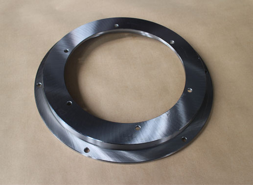
Open type:250.15.0375.013 Typ 13/400
-
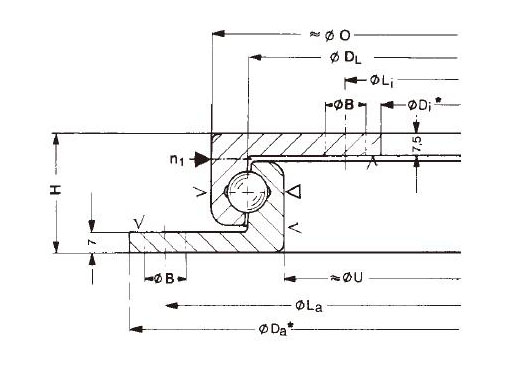
Dimension
di:234mm
Da:400mm
H:40mm
-
Mounting
Li:260mm
La:380mm
-
Basic Load Ratings
Cr:-kN
Cor:-kN
-
Gear Teeth
m:-mm
z:-mm
-
Equivalent Model
Mass:9.6kg
- Features
- Mounting
250.15.0375.013 slewing bearing specifications:
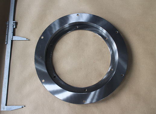
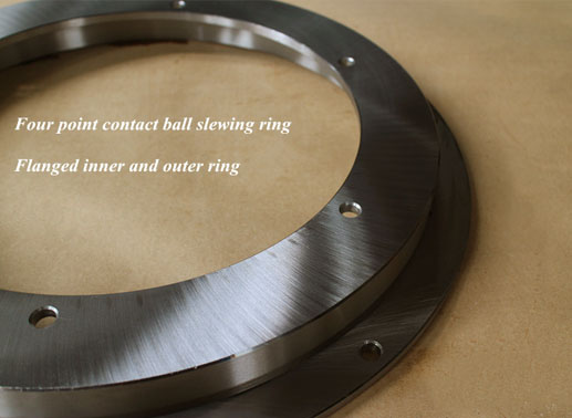
Type of guide Steel ball Space retainer Yes Material 42CrMo/50Mn Standard lubrication method Grease lubrication Oil hole Yes Sealing NBR sealed both sides Surface treatment Available Radial clearance 0 ~0.02 mm Running accuracy Max 0.02mm Working temperature -20℃ ~ 80℃ This 250.15.0375.013 Typ 13/400 slewing bearing belongs to light series four point contact ball slewing ring, but its structure is different with VLU slewing bearing type. It’s equivalent to Rollix model L4-13P8Z**.
250.15.0375.013 ball slewing bearing features:
1. Single row four point contact ball slewing bearing, can take radial and axial loads at the same time.
2. Flanged rings with mounting holes, reduce total weight of device.
3. High quality raw material, which can ensure bearings hardness and wear resistance.
4. Hardened raceway, extend bearings service life.
6. Customized size, structure and surface treatment available.KD210 Type13 light series slewing bearing models
Part No. Da (mm) Di (mm) H (mm) La (mm) Li (mm) O (mm) U (mm) Weight (kg) 250.15.0375.013
Typ 13/400400 234 40 380 260 348 298 9.6 250.15.0475.013
Typ 13/500500 334 40 480 360 446 396 13.1 250.15.0375.013 slewing ring mounting instructions:

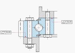
1. Make sure the mounting surface is flat and clean, and free from burrs or
rough edge.
2. The unhardened zone is marked with an “S” on the slewing ring, it must be positioned outside the main load-carrying areas.
3. Commissioning of the slewing ring under sufficient load.
4. Adjust the backlash of gear and recheck it after final tightening of the bearing.
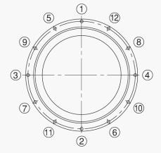
5. Fastening bolts. Place the bearing onto connecting structure and align the screw holes. Screw all the bolts in the holes first and follow the order as shown in diagram when tightening bolts in diagonally opposite sequence. Do not tighten bolts randomly.
6. Check the installation by rotating the assembled bearing arrangement. The torque should not show any excessive variation or “tight spots” during rotation.