352224
2019-04-29
-
Part NO.
Open type:352224
-
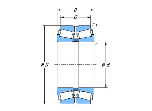
Dimension
d:120mm
D:215mm
T:132mm
-
Mounting
-
Basic Load Ratings
Cr:700kN
Cor:1390kN
-
Equivalent Model
Mass:19.1kg
- Features
- Mounting
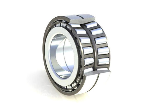
352224 double row tapered roller bearing features:
1. Support heavy radial loads, axial loads in both directions.
2. Composed of a double cup, two cones and a cone spacer.
3. Easy installation, with mounting holes on both inner and outer ring.
4. Can be used either as locating or nonlocating bearings.
352224 double row tapered roller bearing installation instructions
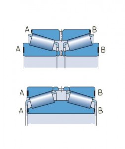
Components of double row tapered roller bearings can also be mounted separately. The individual rings of one bearing must be mounted in the correct order and position. They must also not be mixed with those of another bearing.

Components of one bearing are marked with letters that indicate their correct order and position (Fig 1). All components of one bearing are marked with the same serial number.
BRS double row tapered roller bearings are ready-to-mount units, manufactured with the predetermined axial clearance or preload. The complete bearing must be mounted in the chock, after which the chock together with the bearing is slid onto the neck. This means that the bearing inner ring must have a loose fit on the neck, although it should technically have a tight fit due to the circumferential load. With a loose fit, the inner ring will inevitably creep on the neck and the neck will undergo heating and wear in this case. However, wear can be restricted by good lubrication.Load zone
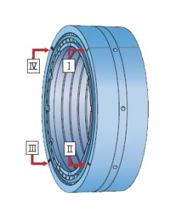
In the majority of rolling mill applications, the direction of a radial load is constant. Depending on the ratio between axial and radial loads, usually only approximately one quarter of the outer ring raceway is under load. Therefore (Fig 2):* Outer rings are divided into four zones identified by a marking I to IV on the outer ring side faces, on request.
* Markings for zone I are also joined by a line across the outside surface
* For initial mounting, zone I (line across the outside surface) should be positioned in the direction of the load.
* Depending on the operating conditions, after a period of service the outer rings should be turned through 90° so that a new (the next) zone becomes the loaded zone.