8038/670
2019-04-29
-
Part NO.
Open type:8038/670
-
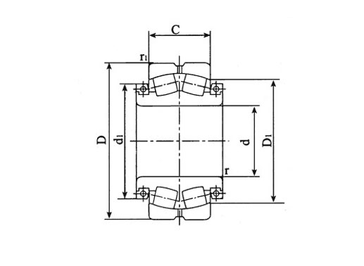
Dimension
d:670mm
D:980mm
B:350mm
C:230mm
-
Mounting
-
Basic Load Ratings
Cr:6440kN
Cor:14000kN
-
Equivalent Model
Mass:800kg
- Features
- Mounting
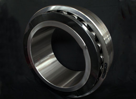
8038/670 split spherical roller bearing features:
1. Comparable capacity to solid bearing.
2. Internally self-aligning.
3. Simplify the replacement and installation.
4. Reduce downtime of machinery and plant.
5. Reduce assembly and maintenance costs.
8038/670 split bearings applications
Cold rolling tube mill
Cold pilger tube rolling mill
Pilger mill crankshaft
Cold pilger rolling
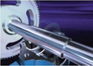
8038/670 split spherical roller bearing installation instructions
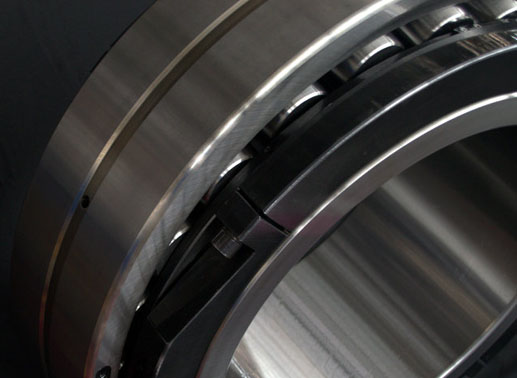
Bearings must be disassembled before assembling into position.
To ensure proper operation, split spherical roller bearings must be clamped onto a clean, uniform shaft that is within the specified tolerance limits and adequately lubricated. Also, the inner and outer ring halves and roller assemblies are not interchangeable with other bearings, and must be matched according to the markings on the rings during installation.

1. Place the housing base or flange lower half into position.
2. Place the inner race at the correct position on the cleaned shaft.
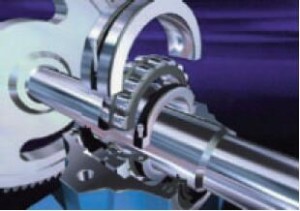
3. Fit the clamping rings then progressively tighten all screws. Tap down each half of the inner race and clamping rings
all around the shaft using a rubber hammer. Re-tighten the screws.
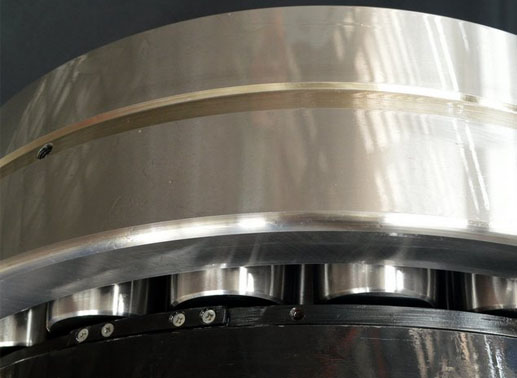
4. Assemble the cage and roller assembly around the inner race, then coat them with grease.
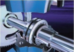
5. Fit the remaining parts, finishing with the upper outer ring half.
6. Lower the shaft in order to subject the bearing to load.
7. Secure housing cover.